1 - Abstract
2 - Introduction:
The aim of this report is to introduce
the steps and procedures of the ENGR 312 Analysis and computations project,
entitled: Application of Cubic Splines. The project represents an introductory
study for the MENG490 thesis students in their project to design a solar
powered car. This report gives an introduction to solar cars and their
history, in addition to the concept of solar-powered car sand their design.
It also gives a background about some design concerns, such as: solar cells,
aerodynamics and drag force.
By using a FORTRAN77 program to make cubic
splines interpolation, some points were introduced to interpolate different
points on the car surface. Finally, a final sketch for the car is done
using MS Excel.
Such a design requires considering some
important case studies; such as: drag calculations, aerodynamic body and
other design cases to maximize the surface area in order to get the maximum
power from the solar cells.
Key words: design of solar cars,
cubic splines interpolation,
FORTRAN 77,aerodynamic
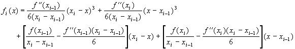
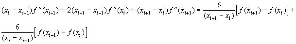
Cubic splines interpolation is the most
efficient method of interpolation. It includes entering a number of points.
The following examples clarify the use of cubic splines.
1 - The car should be designed
in order to maximize the area exposed to sun light in order to achieve
maximum power.
2 - The car shape should
be so-called an aerodynamic shape in order to achieve minimum wind resistance,
or the so-called drag force.
3 - The car should be as
light as possible, because the power expected from the solar cells is not
that much. In addition, most of this power will be utilized to overcome
friction and drag.
A body immersed in a flowing fluid is acted
on by both pressure and viscous forces from the flow. The sum of the forces
(pressure, viscous, or both) that acts normal to the free-stream direction
is the lift, and the sum of that acts parallel to the free-stream
direction is defined as the drag. These definitions are perhaps one
of the famous conclusions of the famous Bernoullis equation, which is
one of the fundamental laws governing the motion of fluids. It relates
an increase in flow velocity to a decrease in pressure and vice versa.
Bernoulli's principle is used in aerodynamics to explain the lift of an
airplane wing in flight. A wing is so designed that air flows more rapidly
over its upper surface than its lower one, leading to a decrease in pressure
on the top surface as compared to the bottom. The resulting pressure difference
provides the lift that sustains the aircraft in flight. The velocity of
a wind that strikes the bluff surface of a building is close to zero near
its wall. According to Bernoulli's principle, this would lead to a rise
in pressure relative to the pressure away from the building, resulting
in wind forces that the structures must be designed to withstand.
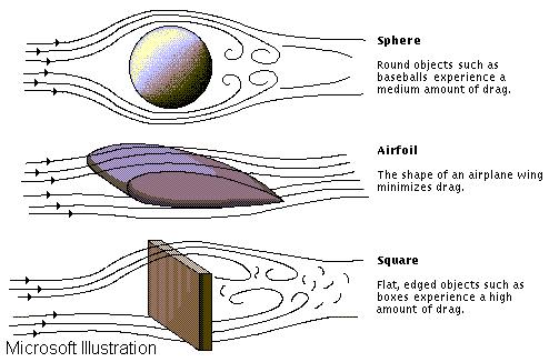
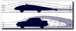
Another important aspect of aerodynamics
is the drag, or resistance, acting on solid bodies moving through air.
The drag forces exerted by the air flowing over the airplane, for example,
must be overcome by the thrust force developed by either the jet engine
or the propellers. These drag forces can be significantly reduced by streamlining
the body. For bodies that are not fully streamlined, the drag force increases
approximately with the square of the speed as they move rapidly through
the air. The power required, for example, to drive an automobile steadily
at medium or high speeds is primarily absorbed in overcoming air resistance.
The following examples illustrate the
importance of considering drag when designing a car
Solar cells made from thin slices of crystalline
silicon, gallium arsenide, or other semiconductor materials convert solar
radiation directly into electricity. Cells with conversion efficiencies
in excess of 30 percent are now available. By connecting large numbers
of these cells into modules, the cost of photo-voltaic electricity has
been reduced to 30 cents per kwh, about twice the rate that the largest
U.S. cities were paying for electricity in 1989. Current use of solar cells
is limited to remote, unattended low-power devices such as buoys and equipment
aboard spacecraft.
In order to design the exterior shape of the solar car, we had to consider the previously mentioned factors, which are:
1 - The design must maximize
the amount of surface area exposed to sunlight to obtain maximum power.
2 - The design of the car
must have an aerodynamic shape to minimize the amount of drag to
which the car is exposed.
3 - The car surface should
have smooth gradual curves to have an aerodynamic body of low wind resistance.
Solar cars have several unique shapes.
The following figure shows the most famous and well-known shapes:
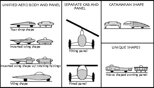
We finally decided to select the wing
shape design. This is because we have found out that most of the universities
tend to design this shape. In addition, it is perhaps the easiest one in
manufacturing. In fact, our shape was not a simple copy for that one; we
introduced some modifications.
Following is the design we set for ourselves:
Position Length (LTR) or Height from the
ground
Entire frame 5.8 m
Wheels 25 cm diameter, 10 cm thickness
Driver cabin height 38 cm
Full height 1.48m
Tail length 3.4m
The tail is taken to be a straight line.
The cross section of the car is taken as an ellipse of changing dimensions.
Thus, the main concern for us became the parts in the front and the drivers
cabin. Using AutoCAD, we estimated some key points along the x-y plane,
considering the left side of the coordinates as the y-axis, and the x-axis
will be the direction along the ground.
After defining these dimensions, a rough
sketch was drawn by AutoCAD. By offsetting and dimensioning, the following
values were obtained.
X coordinate (cm) Y coordinate (cm)
20
89.7261
40
98.296
70
107.2946
90
111.0367
110
113.8179
120
115.0542
These numbers were processed into the
computer program, asking the program to:
a - get the interpolations
of every x point (with 1 cm increment from the first value).
b - get the angle of inclination
of the tangent at the point
Then the output data is used to plot the front section surface.
The same will happen with the driver cabinet. However, since the cabinet will not be covered with photo-voltaic cells, there is no need to calculate the angle of inclination.
X coordinate cm
Y - coordinate cm
120
115.0542
140
136.0397
160
149.3282
180
150.6931
200
143.0437
240
130.2249
260
115.0293
Concerning the tail, the angle of
inclination is known since it is a simple straight line relation.