THE
AMERICAN UNIVERSITY IN CAIRO
Engineering Department
General Electrical Engineering
Application Project
Power Factor Improvement
Based on a study done for
an industrial plant
Presented to:
Dr. Mahmoud Gilany
Presented by:
Moataz Mohammad Attallah
I-Abstract:
The aim of this technical report is to introduce a summary
for a study done by a public sector company for power factor improvement.
This report includes an electrical engineering background about the problem
of power factor, including: the causes, the consequences, the economical
importance for the company and for the country as well, and the theoretical
solution for solving that problem.
The report links the theoretical solution with the real applicable
solution through the study done by the organization for energy planning.
This study includes a nine months research done by the researchers and
the electrical engineers, that represents an ideal methodology for solving
this problem starting from defining the magnitude of the power factor problem
until designing the equipment that can solve that problem.
The report represents all the previous points in simple terminology,
according to the objectives of the course ENGR 318 (general electrical
engineering).
II-Table of Contents:
Topic Page
Introduction 3
Objectives 5
Theory 5
Description of Experiments and Apparatus 6
Procedure (work plan) 7
Results 9
Discussion 10
Recommendations 10
References 10
III-Nomenclature:
Symbol Meaning Unit
S Apparent (total) Power kVA (VA = Volt Ampere)
P Active (real) power kWatt
Q Reactive power kVAR
Vline Line Voltage kVolt
Vphase Phase Voltage kVolt
Iphase Phase Current A (A= Amperes)
cos f Power Factor determines the amount utilized of S
f Phase Angle angle between the current and the voltage Radians
w Angular frequency (w=2pf) rad/sec
C Capacitance Farad
Xc Capacitive reactance Ohms
Vrated Rated voltage for a device kVolt
IV-Introduction:
Industrial plants usually pay large fines because of any large
inductive loads in their factories. Inductive loads result from the storage
of energy in magnetic fields, which occurs in coils of wire, such as in
motor windings and transformers. To decrease high electricity bills resulting
from these large inductive loads, capacitors may be installed at the facility
to increase the power factor.
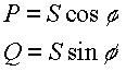
Power factor is the ratio of active (real) power to apparent
(total) power.
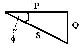 (1) P.F.=cos
F=P/S
(1) P.F.=cos
F=P/S
Apparent power is made up of two components, called active
power and reactive power. Reactive power, whether inductive or Capacitive,
always acts at right angles to active power. Reactive power is not useful
in an industrial setting, as it does no real work when supplied to motors
or other electrical devices. Power distribution company in Egypt bill customers
for how much reactive power they use, and since reactive power supplies
no benefit to the manufacturer, it is desirable to reduce or eliminate
the reactive component of power that the manufacturer uses.
For any three phase factory, the amount of the active power
required from the source to run its machines is:
 (2)
(2)
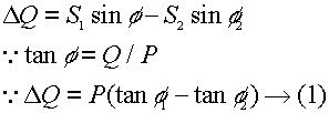
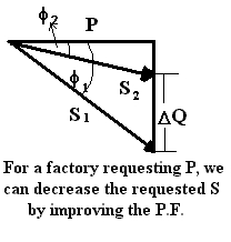
Assuming that the amount of apparent power supplied to the factory
constant, and that the load consumption of reactive power becomes less,
then the current becomes smaller. Hence, voltage drop, power, and energy
losses decrease. This enables the factory to add more loads using the same
power stations.
The problem with low power factor exceeds the commonly known
consequences, such as: power, energy, and voltage losses. Along with these
consequences, the active power produced will decrease. This mainly affects
power stations, either the main stations or sub-stations installed in the
plant. They have to work faster, and large amounts of fuel will be consumed
to make up for the reactive losses.
Since the current is inversely proportional to the power
factor, it can be proved that power losses are inversely proportional to
the square of the power factor.
P loss = I^2 R (3)
Thus power factor improvement is a method to reduce network
losses, either active power of reactive power.
Both Power consumers and suppliers are interested in power
factor improvement. For consumers, they have to decrease the economical
losses because of the high fine assigned by the power supplier because
of the low power factor. In Egypt, some companies pay large fines because
of the low power factors in case the power factor is below 0.9 along with
the power bill due to the normal consumption. For the suppliers, the request
for power will decrease resulting in a decrease in the amount of fuel used
in the power stations.
It is known that the power factor for a fully loaded induction
motor ranges between 0.75 to 0.85. When the motor load is below rated,
the power factor drops since the motor draws less active power and about
the same reactive power.
In conclusion, low power factor results in:
1- Large power losses in the lines, transformers and generators.
2- Extra copper and aluminum good conductors have to be used to
minimize
losses.
3- Smaller capacities of transformers and lines must be used to
avoid power losses due to the large current flowing out.
4- Lower network voltage due to the large current.
There are some factors that motivate the companies to improve their
power factors, these are:
1 - The economical importance (elimination of the power
factor penalty):
Some factories pay large fines because of their low
power factor, sometimes larger than the normal power consumption bill.
In Egypt, the power distribution companies give bonuses for the companies
of high P.F. (more than 0.9)
2 - Reduction of internal power losses:
These losses may take the shape of reactive power, or power, energy,
and voltage losses.
3 - Payback period:
After installing the equipment needed to correct the power
factor, there will be a very short payback period. This means that the
cost of the equipment needed to improve the power factor will be recovered
in a very short period. On the other sides, the costs of the equipment
are by far less than the fine required from the company due its low P.F.
Based on the study, the payback period is 6 months.
V-Objectives:
The aim of this report is to introduce an ideal methodology
for power factor improvement of an industrial plant.
The shape of the study was as follows:
1-Introduction:
a - Description of the low power factor problem.
b - Description of the industrial plant, and its activities.
c - Power consumption data.
2-Work plan:
Phase A includes:
a - Measurements.
b - Data analysis.
c - Recommendations.
d - Equipment design, sizing, and location.
Phase B includes:
a - Detailed design.
b - Installation.
c - Evaluation and supervision.
VI-Theory:
A simple idea for the power factor improvement is the use
of a capacitor in parallel to the factory to decrease the reactive power
losses.
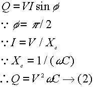
It is known that in the capacitor the current leads the voltage
by a 90° angle. Given that the active and reactive powers are given
as:
 (4,5)
(4,5)
Therefore, for the capacitor P = 0, while Q = -S (because it is
the current that leads the voltage).
The meaning of the negative reactive power is that the capacitor
can be used as a source of negative reactive power.(i.e., it reduces the
reactive power)
 (6)
(6)
 For the capacitor,
 (7)
(7)
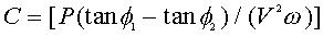
equating (1) and (2) together gives the value of the capacitance
of the capacitor to be installed in parallel to the factory.
 (8)
(8)
VII-Description of the used devices:
Conducting such a study requires collecting of essential data,
because dependence on the bills of the distribution company might lead
to false design.
The used device is called:
BMI 3030 A Power Profiler
(Energy and harmonic analyzer)
This device is a basic measuring device that measures:
· True RMS of voltage and current.
· Active power (kW)
· Reactive power (kVAR)
· Apparent power (kVA)
· True power factor (PF)
· Harmonic content of the current and voltage
The device records the data on 3.5² floppy disks.
VIII-Procedures (work plan):
PHASE A
1-Measurements:
refer to the section of the used devices
2-Data analysis:
The data retrieved from the measuring device calculates the above
mentioned quantities. By analyzing these data, some important facts are
highlighted, such as:
· The power factor calculated by the distribution
company was less than the actual power factor. This means that the distribution
company measuring devices are not working efficiently and they need to
be replaced.
· Some parts of the plan have high P.F. because
they are pure resistive loads.
· Some motors and transformers are partially
loaded.
3-Recommendations:
The P.F. problem can be improved basically without the need
to install any capacitors by reducing the amount of reactive power consumed
in motors and transformers. This may be achieved by:
· Installing motors of proper rating, speed,
type and size according to the load and the operating of the machine.
· Replacing large induction motors with synchronous
motors.
· Replacing lightly loaded motors or transformers
with others of smaller ratings.
· Cutting down no load operations of motors through
limiters and electrical interlock that disconnect the motor when the operation
is terminated. For slightly loaded motors, the electric interlocks might
be used to shift the windings from delta to star.(In star Vline =Ö3
Vphase)
· Produce additional load on the lightly loaded
motors through electrical process.
These points can be explained as follows. The voltage of the
motor determines the self-induced e.m.f of the motor windings. Thus,
the higher the voltage and the lower the load on the motor, the higher
the induced e.m.f. and the lower the P.F.
The second problem is the transformers; transformers consume
about 30% of the reactive power of the system. Transformers carrying less
than 30% of their rating cause enormous losses in the P.F. Thus they should
be loaded within a limit of 30è 70% of their ratings.
Mostly the power factor improvement equipment is capacitors.
Their advantage is that they have very small active power losses (0.0025è0.005kW
per kVAR). They are simple and easy devices and they do not have rotating
parts that may produce inductive reactance. Their shortcomings are
their relatively small life (8à10 years), the potential danger of
short-circuit (wiring) of the capacitor in case the voltage exceeds their
rated voltage by 1.1Vrated, and that they are unrepairable.
4-Equipment design, sizing and location:
The design of the capacitors depends on the P.F. as above mentioned
in the theory section. The difficulty usually lies in the locating the
capacitors.
For any plant, the overall average P.F. is different from
the P.F. for every sub-station or even each load section of the factory.
Thus there is a very important factor that should be considered, which
is:
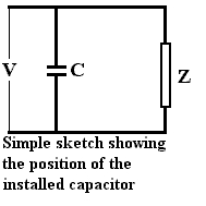
The position of the installed capacitor:
1-Input side of the main power feeder switch gear: This method is
less costly for the user than the capacitor used for low voltages. However,
it does not eliminate the problem; in a way it increases the overall power
factor of the whole plant, but all the inductive reactive currents are
still circulating between the factory loads, sub-stations, and the capacitors.
Despite improving the power factor, power losses are not reduced to a satisfactory
range. Moreover, the cost of switch gears is much expensive when the capacitor
is connected to the main power feeder.
2-Input side of each load center: This method is usually used with
the third one. The capacitor is installed at the input side of each load
center. The total capacitance is divided on all the load centers. Regardless
of the fact that the inductive reactive currents will still be flowing
between the machines, load center, and the capacitor but they will never
reach the main power feeder.
3-Low voltage side of each load center: This method is efficient
in both eliminating the low P.F., because the inductive reactive current
will be flowing between the motor and the capacitor. However, the price
of the capacitors in this case is relatively high because of its small
capacitance, thus increasing the payback period.
PHASE B
1-Detailed design:
2-Installation:
It is not intended to go through the technical details of
the design and installation, however some points must be mentioned that
suit the objectives of the course.
The equipment needed for the P.F. improvement is:
· Switchboard panel of enameled steel (enclosure
IP 30) .
· Three phase Circuit breakers (air type).
· Copper bus bars.
· Capacitors according to the value required
(capacitance is measured here in kVAR).
· Power factor meter and controller.
· VAR meters
3-Evaluation and supervision:
The capacitors should have the following specifications:
· There is a need for substitute capacitors to
be used in case of maintenance.
· Each unit should contain discharge resistors
to bleed off residual voltages after the disconnection of the power. The
discharge time should be around 5 minutes.
· Vrated should be 1.1 Vrequired-
· Capacitance variation with temperature should
be minimized, either by cooling the capacitor or selecting a capacitor
of good temperature-capacitance properties.
· They should be adapted to automatic step systems
controlled by the power factor meters.
· IP 45
IX-Results:
Quality Before P.F. improvement After P.F. improvement
Average annual P.F. 0.77 0.95
Active power (P) 2280 kW 2280 kW
Apparent power (S) 3800 kVA 2400 kVA
Annual consumption 5274 MWh 5116 MWh
X-Discussion:
Since the reactive power in factories is due to inductive
loads, then they might be compensated by Capacitive reactive loads because
they cancel each other. Thus the solution to decrease the inductive reactive
power is to increase the Capacitive power because they cancel each other,
and hence decreasing the overall reactive power, which is considered as
a kind of losses of the total supplied power.
XI-Recommendations:
The problem of power factor is not a smoldering problem that
arises all of a sudden. Undoubtedly, this problem is a result of poor electrical
engineering design. The problem might be avoided from the start by considering
the following facts:
1-Once the motor is loaded less than its rating, the used active
power is less. Thus the reactive power takes a large share of the apparent
power. Therefore, motors of adequate rate, speed, type, and size should
be installed according to the
load and the operating of the machine.
2- As previously mentioned, transformers consume about 30% of the
reactive power of the system. Transformers carrying less than 30% of their
rating cause enormous losses in the P.F. Thus they should be loaded within
a limit of 30è 70% of their ratings.
XII-References:
Abdel-Aziz, Abdel-Aziz M. Power Factor Improvement
Project. Organization for Energy Planning, Cairo. 1993
Lipkin, B.Y. Electrical Equipment for Industry. Higher
School Publishing House, Moscow. 1967.
Directory
Home